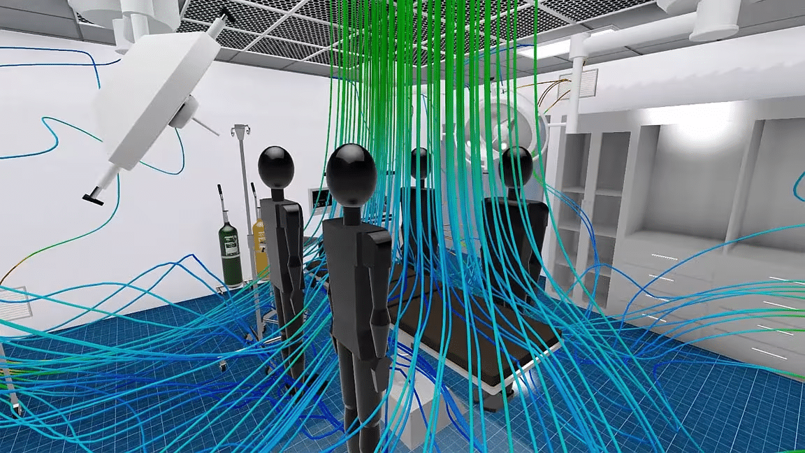
Computational Fluid Dynamics (CFD) is the analysis of fluid flow using numerical solution methods. CFD allows experts to analyze complex problems involving several interactions such as fluid-gas, fluid-fluid, and more commonly, fluid-solid interactions.
Engineering fields where CFD analyses are frequently used are aerodynamics and hydrodynamics. In these fields, CFD simulations allow experts to study quantities such as lift and drag or field properties as pressures and velocities. Fluid dynamics is the study of the effect of forces on fluid motion. It is involved with physical laws in the form of partial differential equations. Sophisticated CFD solvers transform these laws into algebraic equations and are able to efficiently solve these equations numerically.
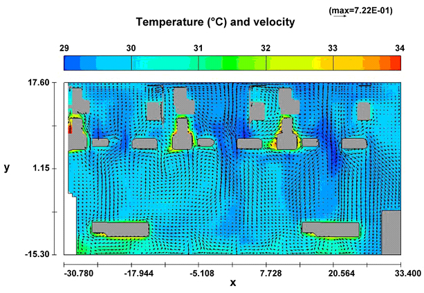
Figure 1. Temperature (°C) and velocity contour plots obtained from CFD simulation
Computation fluid dynamics (CFD) is an engineering tool used to simulate the action of thermo-fluids in a system. It is used in many industries in their development work to analyse, optimise and verify the performance of designs before costly prototypes and physical tests. This article discusses several CFD software and their applications in the HVAC industry.
Computational Fluid Dynamics (CFD) software
The applications of CFD analysis software are virtually endless. CFD programs are widely utilized in the aerospace, auto manufacturing, and shipbuilding industries and HVAC etc. Other sectors where CFD modelling software comes in handy include biotechnology, urban planning, plumbing fixture manufacturing, water management systems, civil engineering, video game development, and many others.
Here is a list of several Computational Fluid Dynamics (CFD) software:
⦁ ANSYS by ANSYS.
⦁ Autodesk CFD by Autodesk.
⦁ OpenFOAM by the OpenFOAM Foundation.
⦁ PowerFLOW by Simscale.
⦁ Simscale by simscale.
⦁ COMSOL Multiphysics by COMSOL INC.
⦁ IVRESS by Advanced Science & Automation Corporation.
⦁ FLOW-3D by Flow Science.
⦁ SolidWorks Flow Simulation by Dassault System.
⦁ Altair HyperWorks Suite by Altair Engineering.
⦁ Simulation X by ESI ITI.
⦁ PIPESIM by Schlumberger.
⦁ Advanced Simulation Library (ASL) by Avtech Scientific.
⦁ Elmer by CSC-IT Centre for science.
⦁ SU2 By Stanford university unstructured project
⦁ Ingrid Cloud by Adaptive Simulation.
⦁ Abaqus CFD by ABAQUS Inc.
Most of the CFD software providers (Ansys, SolidWorks, Comsol, Abaqus, etc.) cover HVAC applications as they have been on the market for long and their products are mature.
SimScale might be the best solution for HVAC because it is cloud-based. It comes with added benefits; compatible with any laptop/PC in Chrome/Mozilla web browser. It also has collaboration options and live support, and gives users access to a community.
HVAC INDUSTRY CFD CORE APPLICATION
The 4 type of applications that CFD engineers are working on within the HVAC/Construction industry include:
1. Air Ventilation & Thermal Comfort for space
The sustainable design of a complex heating, ventilation and air conditioning (HVAC) system will aim to maximize thermal comfort by considering details such as
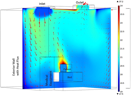
Figure 2. Temperature distribution contour for space.
⦁ space temperature,
⦁ space humidity,
⦁ expected occupancy levels and body heat,
⦁ mean age of air within an interior space,
⦁ ventilation of pollutants such as CO within a car park,
⦁ relationship with the external environment including solar loading and shading, and
⦁ Heat loss through the building envelope such as through doors, windows and walls.
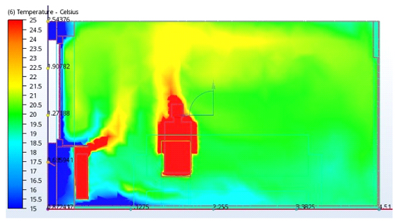 Figure 3. Thermal airflow contour diagram.
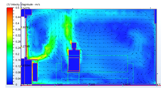
Figure 4. Air Velocity flow diagram.
When Temperatures and potential pollutants throughout a building are modelled in CFD, engineers are able to iterate on their HVAC design cost efficiently and can quickly consider all key design trade-offs so that they can arrive at the optimal HVAC set up for a specific building project (considering both cost, comfort and energy efficiency).
2. HVAC Equipment Design process
Design of equipment for heating, ventilation and air conditioning (HVAC) is a mature industry, and so there is increasing pressure to differentiate increasing their energy efficiency while concurrently reducing manufacturing costs. CFD simulations allow design engineers to assess key product performance metrics such as noise levels, energy efficiency and reliability across a wide range of HVAC equipment such as:
⦁ Air cleaning equipment
⦁ Air conditioners
⦁ Air handlers
⦁ Burner design/boilers
⦁ Chillers
⦁ Diffusers
⦁ Heat exchangers/coils
⦁ Humidifiers/dehumidifiers
⦁ Heating equipment
⦁ Pumps/blowers, fans and compressors/exhausters
Refrigerators
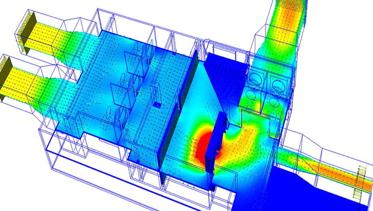 Figure 5. HVAC equipment airflow contour diagram.
By simulating the performance of HVAC equipment in a virtual prototype subject to a variety of environmental conditions and under different loads, manufacturers can avoid having to build costly physical prototypes during their preliminary design. Furthermore, manufacturers are able to identify potential problems as early as possible (at a time in the design cycle when mistakes are still relatively inexpensive to fix!).
Equipment manufacturers are also under pressure to optimise the shape of HVAC components so that they can fit into confined spaces. Like in the automotive industry, HVAC engineers are often working with design constraints and are beginning to use CFD to help fit their components into limited spaces whilst still optimising performance (i.e. minimising pressure drop within their equipment).
3. Fire & Smoke Propagation
Fire and smoke propagation is a dreaded occurrence in the several industries. Increasingly strict regulations govern the design of fire and smoke management systems for any new building or facility, so developers must ensure their design meets well-defined conditions relating to the:
– Safety of occupants during a fire &
– Structural integrity of the building.
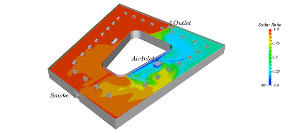 Figure 6. Fire and Smoke air flow diagram
The physical test of a fire scenario is extremely expensive and labour intensive, and also may require consideration of a large number of variables – so engineers are increasingly turning to CFD simulations to undertake the bulk of the legwork in their fire/smoke projects. As a fire engineer, we must first understand the physical phenomena of how fires start, propagate and impact on the structure, and how we can best simulate the physics within our CFD simulations. Once we have a well-validated CFD model, we are then able to commence systematic parametric studies so that we have considered all likely fire scenarios and are able to develop a fire mitigation system to:
– optimise emergency evacuation procedures,
– optimise placement of smoke management & firefighting equipment, and
– Ultimately prevent a fire from spreading out of control within the structure.
4. Wind Engineering
The designs of new skyscrapers, bridges, stadiums and landmarks are becoming more difficult as the surrounding environments grow more complex with each new project. Subsequently, engineers and architects must carry out more complex wind engineering analyses to help predict how a building responds to its environment and what changes it will bring to surrounding areas. Engineers in this field are primarily concerned with:
⦁ Understanding the external aerodynamics of a building for all possible wind angles
⦁ Quantifying structural wind loads for all possible wind angles
⦁ Transport and dispersion of pollutants
⦁ Impact of wind-driven rain on balconies and entrances/foyers
⦁ Pedestrian comfort at ground level

Figure 7. building wind flow contour diagram
In Conjunction with carefully planned wind tunnel studies, CFD simulation provides engineers with a cost-effective and insightful tool to better understand all of these key applications while also providing authorities with suitable data to complete environmental impact statements and assess whether new designs meet regulatory guidelines.
In each of these key applications across the construction industry, the use of a virtual modelling approach with CFD provides engineers and designers with the right tool to:
– evaluate and compare a range of options quickly and efficiently,
– reduce the risk of faulty construction and increase the probability of project completion on time and within budget, and
– satisfy all regulatory requirements relating to safety and sustainability.
CFD Benefits
⦁ CFD simulations enable experts to predict the thermal performance of a naturally ventilated room, which may be applied to improve the designing of the inlet size and location of fresh air valve to set the best results to assess thermal comfort.
⦁ CFD allows experts to predict mass flow rates, pressure drops, heat transfer rates, and fluid dynamic forces such as lift, drag and pitching moments. This prediction helps to reduce costs associated with physical experimentation to retrieve essential engineering data.
CFD software continues to play a major in HVAC systems. Businesses have been able to cut costs just by utilizing some of this software during their design process.