WHAT IS CLEANROOM TECHNOLOGY?
Cleanroom describes a controlled environment where pollutants like aerosol, airborne bacteria, and dust are in small amounts. Cleanroom technology requires both technological and operational measures to avoid the potential risk of contamination of products.
The cleanroom has a controlled level of contamination that is determined by the number of particles per cubic meter at the defined particle scale. Outdoor- indoor air in a typical city setting produces 35,000,000 particles per cubic meter, 0.5 microns, and wider in diameter, equivalent to the cleanroom ISO 9 at the lowest point of cleanroom quality.
This article presents all you need to know about cleanroom technology. It’s usually best to start by understanding the difference between the conventional HVAC and cleanroom HVAC.
- Difference between Conventional & cleanroom HVAC
Similar to standard HVAC, the HVAC of a cleanroom controls the temperature and the humidity to different levels of precision to create a comfortable environment. Along with comfort, cleanroom HVACs differentiate themselves from conventional systems by their increased air supply, airflow patterns, the use of high-efficiency filters, and room pressurization.
The increased air supply brings more air changes per hour with HEPA(High-Efficiency Particulate Air) filtered air circulating into the cleanroom many times per hour. In comparison, a conventional HVAC system usually counts two to four air changes per hour, whereas in a cleanroom it can range anywhere from 15 to 250 or more.Cleanroom HVAC designs require knowledge of regulations, cleanliness level guidelines, airflow, room pressurization, temperature control, humidity control, and accounting of the processes taking place inside.
Ventilation ducts are also different and require engineering knowledge. The HVAC must also maintain the appropriate pressure differential in order to prevent air from leaking from a less clean zone to a cleaner zone inside the cleanroom. A cleanroom differs from the conventionally ventilated room mainly in three ways.
⦁ Increased air supply: The increased air supply is an important aspect of particle control. Normal air-conditioning systems are designed for 0.5 to 2 air changes per hour, essentially based on the occupancy level or as determined from the building exhaust levels. In contrast, a cleanroom would have at least 10 air changes per hour and could be as high as 600 for absolute cleanliness. This large air supply in a cleanroom is mainly provided to eliminate the settling of the particulate and dilute contamination produced in the room to an acceptable concentration level.
⦁ The use of high-efficiency filters: High-efficiency filters are used to filter the supply air into a cleanroom to ensure the removal of small particles. High-efficiency filters used in cleanrooms are installed at the point of air discharge into the room. Room pressurization is mainly provided to ensure that untreated air does not pass from dirtier adjacent areas into the cleanroom.
⦁ Room pressurization: The cleanroom is positively pressurized with respect to the adjacent areas. This pressurization is done by supplying more air and extracting less air from the room than is supplied to it.Classification of Cleanrooms
HVAC system design depends heavily on the required cleanroom classification according to ISO 14644-1. Although this standard relies on adopting a certain Air Change Number per hour (ACH), yet thermal loads need to be addressed in early stages of the project taking into consideration all internal and external heat sources.
-
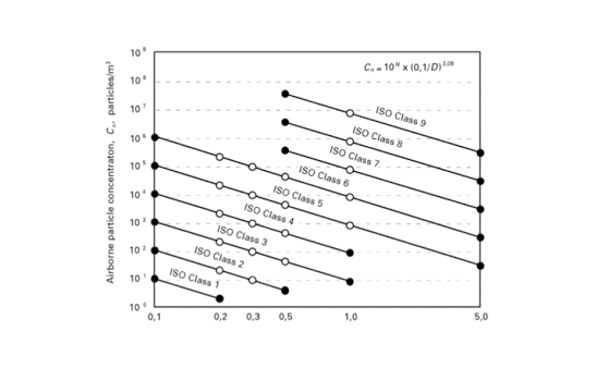
Figure 02: ISO Class Chart It is important to understand that thermal load calculation is not only needed for equipment selection, but it is also required to understand load fluctuations, hence choosing the most feasible HVAC system from initial cost as well as operational cost point of view.

Table: ACH as per ISO ClassCleanroom zoning
There are four types of clean zones in manufacturing sterilized pharmaceutical products. The grade is defined by the type of product and a part of the process which needs to be protected from contamination.The grades can be classified as A, B, C, or D.
⦁ A – Local zone, which is for operations that afford high risk for product quality, e.g. filling, closing, ampoule and bottle opening zones. Usually in such zones is used laminar airflow which provides similar velocity 0.36-0.54 m/s.
⦁ B – zone, which is used for aseptic preparation and fulfil.
⦁ C and D – are clean zones used for less responsible stages of manufacturing sterilized products.Makeup Air and Building Pressurization
Typically many of the critical clean zones have their own dedicated air conditioning systems. While this is a good design strategy, many of the installations rely purely on the recirculation system without paying much attention to pressurization.
Without pressurization, gaseous contaminants can seep into these sensitive rooms through cracks in wall and ceiling joints, cable and utility penetrations, and spaces above drop ceilings and below raised floors.
Positive pressurization is the basis of assuring that uncontrolled and untreated air does not infiltrate the protected area. The ambient air used to provide the positive pressurization must be treated to ensure an environment free of both the gases and particulates.
The recommended minimum amount of positive pressurization gradient is 0.03” to 0.05” (~0.75 to 1.25mm) water column for cleanroom applications. This would generally equate to 3- 8% of gross room volume.
The amount of outside air required is a function of:
⦁ Equipment exhausts and exhaust through toilets, kitchen, pantry, battery rooms etc.
⦁ Leakage through pass through, conveyor openings, strip curtains, airlocks, door undercuts etc.
⦁ Duct leakage, wall and ceiling leakages
⦁ Level of positive pressurization requiredThe HVAC design must optimize the use of makeup air and minimize the uncontrolled air leakages while maintaining the controlled ventilation
AIR PRESSURE GRADIENT
Positive pressurization is maintained throughout the Cleanroom with the highest pressure being in the cleanest area, and it gradually decreases toward the less clean adjacent rooms. This reduces the chance of contaminants from dirty areas entering the cleaner room as the microorganisms will be pushed away by the pressure.
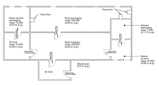 Figure 03: Air Pressure Gradient in Room
Static or active pressure control methods are used depending on the tolerances. Typical tolerance is ±0.01 inches wg. Some semiconductor cleanrooms require a precision of ±0.0025 inches wg. In high precision rooms, the control system must be responsive enough to maintain the differential pressure when doors are opened.
HOW TO CONTROL HUMIDITY IN YOUR CLEANROOM
Controlling the humidity in your cleanroom is crucial, not only to meet government and company specifications, but to protect the integrity of your processes and product. If the humidity is too high, bacterial growth can flourish, metal products or equipment can corrode, photolithographic degradation, condensation, and water absorption can occur. If the humidity is too low, static build-up and discharge can become an issue.
Many products manufactured and processed in a cleanroom environment are moisture-sensitive. For this reason, cleanroom specifications often include relative humidity (RH) control. These control points range from 35-65%RH for year-round operation. These RH levels generally are maintained in a narrow band ±2 % RH at temperatures below 70°F. The effects of higher humidity levels in close tolerance environments can be detrimental to product quality and production schedules.
Humidification is one of the environmental conditions usually specified for cleanroom operations. It is the process of increasing the water vapour content of the air. Common approaches to increase the humidity include:Ultrasonic Humidifier:
An ultrasonic humidifier is a device that uses high-frequency sound vibrations to produce an extra fine water mist that is then expelled to add moisture to the room.The ultrasonic generally has no filter factored into its design. It is considered safer in that there is no hot water present in the unit and therefore no risk of scalding since the unit does not heat the water in any way.
Disinfecting the humidifier becomes even more important than with a warm mist humidifier that does boil the water. Humidity influences a number of factors that could degrade overall cleanroom performance, including:
⦁ Bacteria growth
⦁ Personnel comfort zone
⦁ Static charge build-up
⦁ Metal corrosion
⦁ Moisture condensation
⦁ Photolithographic degradation
⦁ Water absorptionTwo common approaches to humidity control are as below.
⦁ Air Conditioning
Air conditioning lowers the temperature of a surface exposed to the cleanroom airstream below the dew point of that airstream. Excess water vapour condenses, and the resulting air is dehumidified. The air must then be reheated to the proper control temperature and routed to the cleanroom. Standard refrigeration equipment can produce dew points of 40°F (4°C) on a reliable basis.
⦁ Desiccants
In a desiccant system, the process airstream passes through a desiccant medium. The desiccant adsorbs moisture directly from the airstream, and the resulting dehumidified air is routed to the cleanroom.
Desiccant dehumidifiers can produce dew points below 0°F (-18°C), a fivefold reduction in the air moisture beyond what can be achieved with standard HVAC-grade refrigeration systems.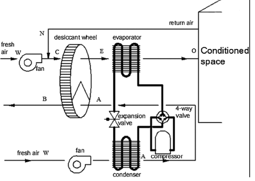 Figure 04: Desiccant System in Clean Room
Supply air and exhaust (return) air
The location of the supply and exhaust (return) air grilles should take the highest priority when laying out the cleanroom.
The supply (from the ceiling) and return air grilles (at a low level) should be at the opposite sides of the cleanroom, to facilitate a “plug” flow effect.Depending on the degree of cleanliness required, it is common for air systems to deliver considerably more air than would be needed solely to meet temperature and humidity design. Airborne particles can be organic or inorganic. Most contamination control problems concern the total contamination within the air.
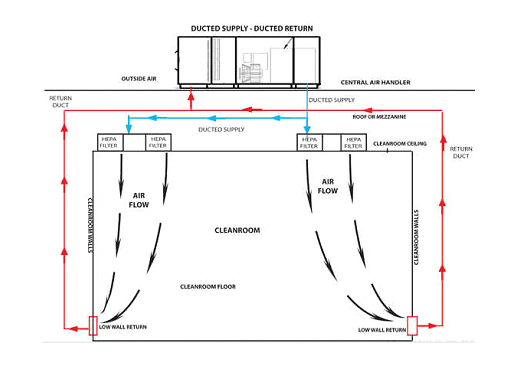 Figure 05: Air Flow Pattern in Clean Room
Particles of varying sizes behave differently, as air moves through a room. Selection of the airflow patterns is a major step in cleanroom design. Because airflow is such an important aspect of particle control, the design of a cleanroom requires careful consideration of air motion and airflow patterns.
The general air patterns are:⦁ Unidirectional (sometimes referred to as laminar flow) is an airflow pattern in which essentially the entire body of air within a confined area moves with uniform velocity and in a single direction with generally parallel airstreams. Clean rooms; class 100 and below have unidirectional airflow pattern.
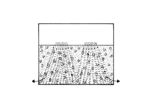
Figure 06: Laminar flow pattern⦁ Non-unidirectional airflow is not unidirectional by having a varying velocity, multiple pass circulation or nonparallel flow direction. Conventional flow clean rooms (class 1000 &10000) have non-unidirectional or mixed airflow patterns.
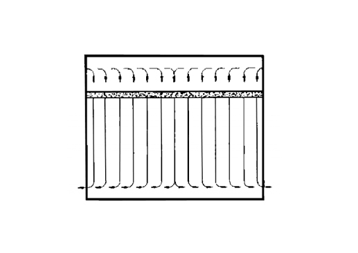 Figure 07: Unidirectional flow pattern
⦁ Mixed patterns combine some of each flow type.
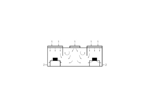 Figure 08: Mixed Airflow pattern
HEPA Filter Setup Flow Evaluation
Cleanroom operation testing firms do cleanroom certification. These firms are designed with sophisticated and calibrated devices necessary for performing Cleanroom Performance Testing (CPT). Several evaluations are included by the cleanroom certification testing procedure; some are required, while others are not obligatory.
HEPA Filter Setup Flow Evaluation: HEPA cleanroom filters are highly powerful air particle filters, used to control microbes and pollutants and preserve environmental standards. The minimal efficacy revealed by means of a HEPA filter when examined using an aerosol is 99.97%. The HEPA setup filter flow test is conducted to find flows, damage and faults in the filters. The evaluation also verifies whether or not they are installed correctly and the integrity of the filters.
Both kinds of flow tests readily available for cleanroom HEPA filters are:
* Complete flow evaluation
* Scan flow evaluation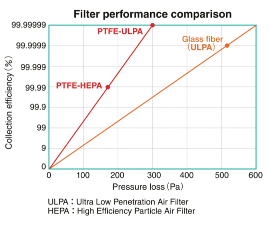 Figure 09: Performance Chart
Noise Criteria
Noise is one of the major issues in a cleanroom, and the designs usually require high degree attenuation and use of acoustic silencers. Cleanrooms is inherently noisy and requires close attention to noise control. This is due to the large requirements of airflow. Cleanroom noise can be attributed to three primary sources:
⦁ Fan noise
⦁ Airflow turbulence
⦁ Process equipment
Airflow noise is due to the turbulence that is typically generated by the introduction of discontinuities in the airstreams (such as elbows or transitions), which is more prominent at high velocities.Cleanroom Ventilation Improvement with CFD Simulation
A well-designed cleanroom environment is necessary for activities performed in a controlled environment, containing a low level of pollutants—a critical requirement for many manufacturing, pharmaceutical, and scientific research applications.
-
 Figure 10: CFD Simulation in Cleanroom
Hence, it is important to understand the role of HVAC principles in a cleanroom environment. One of the best ways to recognize this is by performing simulations. Simulation technology is a cost-effective and time-efficient tool which helps during the design.
There are several configurations available to get the desired airflow and recirculation patterns in order to remove internally generated contaminants.
⦁ Velocity Plot Comparison
Handling laminar and turbulent airflow principles might also be required in specific cases of cleanrooms, which can be analyzed using simulation. Laminar flow usually directs air downward with a constant velocity. This is usually applied over the entire ceiling to maintain a unidirectional flow
⦁ Contaminant Spread Comparison in a Cleanroom Environment
People working in a cleanroom environment face the risk of exposure to chemical vapours if there is any mishandling of chemicals. To approach this problem, experts assume a particular source of contamination and analyze how it spreads in the room. The ultimate aim is to obtain a flow to get rid of the contaminant by regulating it directly to the outlets.